The Science of Speed: Aerodynamics and Drag in F1
Formula 1 pushes engineering to its limits, where every fraction of a second counts. This article explores the Drag Reduction System (DRS), a rear-wing mechanism that cuts drag and boosts speed, showing how aerodynamics, engineering, and future tech drive the relentless pursuit of performance.
Formula 1 has always been at the cutting edge of engineering. Every race car represents the work of hundreds of engineers, designers, and scientists striving to shave fractions of a second off lap times. This is why I have always had an interest in F1. Recently, I had the opportunity to participate in 'F1 in Schools', a competition involving the design and testing of a CO2-powered mini-car, which will soon be raced against the best mini-cars from around the world. This experience required a strong understanding of aerodynamics and the physics involved in vehicle design, including the same scientific principles used by world-renowned F1 engineers.
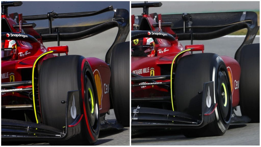
One of the most fascinating areas of F1 technology is the Drag Reduction System (DRS). Introduced in 2011, the DRS gives drivers an opportunity to overtake more easily when travelling within one second of the car in front. The DRS involves a movable flap on the rear wing of the car. When activated, the flap opens, which reduces the wing’s angle of attack, and therefore reduces drag. With less drag, the car can accelerate faster on straights and can achieve a higher top speed, sometimes by as much as 15 km/h to 20 km/h. This provides the chasing driver with an advantage when trying to overtake the car in front.
When a Formula 1 car travels at speeds exceeding 300 kmh, the air around it becomes as influential on performance as the tarmac beneath its tyres. Aerodynamics is the study of the properties of moving gases and how the air and the solid bodies moving through it interact. In F1, aerodynamics serves two main purposes:
- Minimising drag: reducing aerodynamic resistance caused by air flowing over and around the car, allowing for higher top speeds on straight sections of the course.
- Maximising downforce: using airflow to push the car into the ground, increasing grip, stability, and cornering speeds.
The balance between these two forces is what defines a car’s performance. Teams may prioritise higher top speeds at the expense of cornering performance, or could increase cornering ability and stability, but sacrifice top speed. Therefore, finding the optimal balance, which varies between different circuits, is essential for maximising performance during a race weekend.
The drag force equation underpins this relationship, and can be expressed as follows:
where:
- Fd = drag force (N)
- Cd = coefficient of drag (dimensionless quantity)
- ρ = density of air (kg m−3)
- v = velocity of the car (m s−1)
- A = frontal area of the car (m2)
As shown above, the drag force increases with the square of velocity. Simply, by doubling a car’s speed, the drag acting upon it will quadruple. This is why top teams spend so much time optimising the car’s shape in wind tunnels or using computer modelling software such as computational fluid dynamics (CFD). Similarly, downforce is generated through the same principles, particularly through changes in air pressure as it moves over aerodynamic surfaces such as wings, diffusers, and floors. By designing components shaped opposite to aircraft wings, F1 cars generate large amounts of downward thrust that push the car into the ground. At top speeds, an F1 car can theoretically generate enough downforce to drive upside down in a tunnel.
The reduction in drag can be explained using the drag equation mentioned above. By reducing the wing’s angle of attack, the coefficient of drag (Cd) decreases. As a result, the drag force (Fd) is significantly reduced, even though the velocity (v²) remains high.
The following example demonstrates the importance of DRS using the drag force equation:
- Without DRS: Cd = 0.9, velocity v = 80 m s−1 (288 km h−1)
- With DRS: Cd = 0.7
- Assume ρ = 1.225 kg m−3 and A = 1.5 m2
Without DRS:
With DRS:
This represents a reduction of over 1100 N of drag force, highlighting the significant performance advantage provided by DRS.
In terms of engineering, the challenge of DRS lies in designing a mechanism that is both lightweight and reliable. The flap must move quickly (activated by a hydraulic actuator) and be locked securely when not in use. A failure could result in a catastrophic loss of downforce in corners. The actuator is built to withstand high temperatures and vibrations, as certain track surfaces are bumpier than others. Materials such as carbon fibre and PEEK are generally used to manufacture these precise components. To calculate airflow precisely, engineers use complex modelling to simulate the airflow around the rear wing in different configurations. CFD involves solving the Navier–Stokes equations, a set of partial differential equations that describe how fluids flow. These equations are derived from applying Newton’s second law to fluids, accounting for:
- Momentum (inertia) - fluid keeps moving unless acted on.
- Viscosity - internal “friction” within the fluid.
- Pressure - pushes the fluid.
- External forces - like gravity.
Teams use this equation for key aerodynamic analysis, studying airflow while maximising downforce and minimising drag. It is also used to model wake turbulence left behind by cars, which is crucial for overtaking and closely following vehicles. Overall, teams use this equation alongside data obtained from wind tunnel tests to validate designs.
In simplified vector form:
where:
- ρ = density of the fluid
- u = velocity field of the fluid
- p = pressure
- μ = dynamic viscosity of the fluid
- f = external body forces
However, the DRS has sparked debate in Formula 1. Some argue it makes overtaking too repetitive and boring, while others see it as a necessary tool to improve racing by increasing overtaking opportunities. In fact, the 2022 F1 regulations introduced new car designs aimed at reducing “dirty air” (wake turbulence). In the future, F1 may move away from DRS if car designs naturally allow closer racing. Instead, innovations such as active aerodynamics, where car surfaces adjust dynamically depending on track conditions, are taking the spotlight in 2026. Interestingly, this is an area where road car technology (for example, active spoilers) overlaps with F1 research, as the sport expands its relevance to road car technology. The traditional DRS, as used currently, is being replaced or heavily modified under the 2026 regulations. Instead of overtaking only via DRS, a “Manual Override” (MOM) push-to-pass style system tied to the new power units and battery deployment is being introduced. When a following car is close, it may receive extra electrical power to help overtake. Currently, it is still under extensive research and development, but this represents a significant change, as DRS will be eliminated after the 2025 season.
Overall, the Drag Reduction System is more than just a button on the steering wheel. It is the product of physics equations, engineering innovation, and constant CFD modelling. By reducing drag at high speed, it showcases the delicate balance between downforce and drag that defines Formula 1. Ultimately, Formula 1 is not just about racing - it is about innovation. Whether through DRS or the next generation of active aerodynamics, the pursuit of speed will continue to represent the pinnacle of STEM research.
Sources:
General:
The Race (24 January 2025) What is DRS in F1? Drag Reduction System Explained.
Click here to access source.
(Accessed: 17 December 2025).
Rendle, S. (September 2024) How does DRS work?, Raceteq.
Click here to access source.
(Accessed: 17 December 2025).
Barretto, L. (6 June 2024) Explained: From more agile cars to ‘X-mode’ and ‘Z-mode’ – unpicking the 2026 aerodynamic regulations, Formula1.com.
Click here to access source.
(Accessed: 17 December 2025)
Giuliana, R. (October 2024) CFD performance in F1, Raceteq.
Click here to access source.
(Accessed: 17 December 2025)
Images:

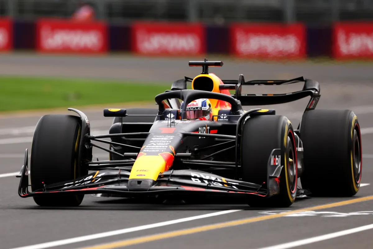
![Image via [Adobe Stock]](/content/images/size/w600/2026/03/IMG_0874.jpeg)
