CT Scans
CT scans are a vital medical imaging technique for diagnosing, treating, and preventing diseases by providing detailed cross-sectional images of the body. By converting X-ray attenuation data into a sinogram, CT scans visualize internal structures with high precision. Advances like helical scanning
Legacy articles aren't reviewed and may be incorrectly formatted.
CT Scans
Brandon Wong
The computed tomography (CT) scan is a medical imaging technique used to diagnose treat and prevent diseases.
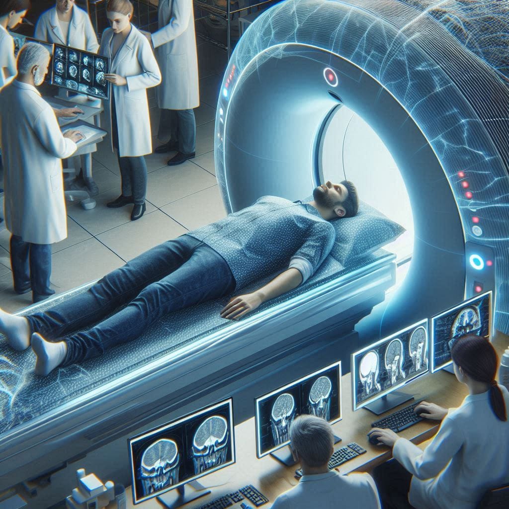
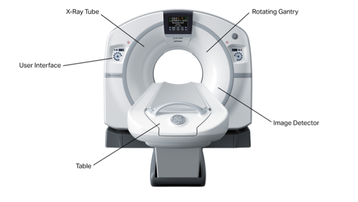
When a CT scan is performed, the patient lies on a table, which is passed through a tunnel. This tunnel contains a rotating X-ray source, with receivers directly opposite it. As the x-rays pass through the patient, tissues of different densities will absorb different amounts of x-rays, attenuating it as it reaches the receiver. X-ray attenuation data taken by the receiver is combined into a sinogram. (Wikipedia, n.d.)
@font-face<br /> {font-family:"Cambria Math";<br /> panose-1:2 4 5 3 5 4 6 3 2 4;<br /> mso-font-charset:0;<br /> mso-generic-font-family:roman;<br /> mso-font-pitch:variable;<br /> mso-font-signature:-536870145 1107305727 0 0 415 0;}@font-face<br /> {font-family:Aptos;<br /> panose-1:2 11 0 4 2 2 2 2 2 4;<br /> mso-font-charset:0;<br /> mso-generic-font-family:swiss;<br /> mso-font-pitch:variable;<br /> mso-font-signature:536871559 3 0 0 415 0;}p.MsoNormal, li.MsoNormal, div.MsoNormal<br /> {mso-style-unhide:no;<br /> mso-style-qformat:yes;<br /> mso-style-parent:"";<br /> margin-top:0cm;<br /> margin-right:0cm;<br /> margin-bottom:8.0pt;<br /> margin-left:0cm;<br /> line-height:115%;<br /> mso-pagination:widow-orphan;<br /> font-size:12.0pt;<br /> font-family:"Aptos",sans-serif;<br /> mso-ascii-font-family:Aptos;<br /> mso-ascii-theme-font:minor-latin;<br /> mso-fareast-font-family:Aptos;<br /> mso-fareast-theme-font:minor-latin;<br /> mso-hansi-font-family:Aptos;<br /> mso-hansi-theme-font:minor-latin;<br /> mso-bidi-font-family:"Times New Roman";<br /> mso-bidi-theme-font:minor-bidi;<br /> mso-font-kerning:1.0pt;<br /> mso-ligatures:standardcontextual;<br /> mso-fareast-language:EN-US;}.MsoChpDefault<br /> {mso-style-type:export-only;<br /> mso-default-props:yes;<br /> mso-ascii-font-family:Aptos;<br /> mso-ascii-theme-font:minor-latin;<br /> mso-fareast-font-family:Aptos;<br /> mso-fareast-theme-font:minor-latin;<br /> mso-hansi-font-family:Aptos;<br /> mso-hansi-theme-font:minor-latin;<br /> mso-bidi-font-family:"Times New Roman";<br /> mso-bidi-theme-font:minor-bidi;<br /> mso-fareast-language:EN-US;}.MsoPapDefault<br /> {mso-style-type:export-only;<br /> margin-bottom:8.0pt;<br /> line-height:115%;}div.WordSection1<br /> {page:WordSection1;}
Figure 1: Features of a CT scanner (Twomey Consulting)
Each column of the sinogram represents a single row in the projection image, arranged in increasing angular order. The horizontal axis represents the angle of the x-ray detector and the vertical axis represents the distance from the tunnel centre within the detector row. The brightness of different points shows the density of different positions based on x-ray attenuation. (Kalke & Siltanen, 2014)

Figure 2: Example sinogram of a disc (Kolibril)
For example, the sinogram of a disc looks like a sin wave, because density is concentrated towards a certain position in the object space as the receiver rotates. Brightness of the sin wave decreases towards the edges as the less x-rays are absorbed at the edges of the circle. (Kolibril, 2022)
Sinograms are interpreted using a tomographic reconstruction. This converts the attenuation data into a function of position in the object space from a function of angle and position with respect to the receiver. Mathematically this is done using the Radon and Fourier transform (Kolibril, 2022). This direct conversion is known as filtered back projection, but since this can be susceptible to noise and streak artifacts, modern reconstruction algorithms use iterative reconstruction. This technique converts the sinogram data to an image back and forth multiple times, checking if the conversion is correct. Data from old scans are also used. This means, however that much heavier computational load is needed. (Radiology Slides, 2023)
In the final CT radiograph formed, the x-ray attenuation of each point in the object space is divided into voxels. The Hounsfield unit is used to describe the radiodensities of different points, ultimately represented relatively with the brightness on the greyscale image. (Wikipedia, n.d.)
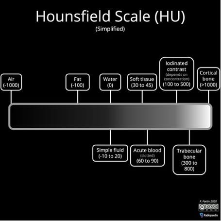
Figure 3: Hounsfield scale with numbers for common tissues (Radiopaedia)
Previously, CT scans were performed sequentially, that means the table is moved to a certain position for collection of data, and then moved to another position. (Terrier, et al., 2012) Nowadays, helical CT scans are performed, in which the table is continuously moved through the tunnel scanner, creating spiral data with less gaps, preventing tumors and abnormalities from being missed and speeding up the process. Multi-slice CT scanners quicken the process even more, capturing data from multiple receivers at once. (Fishman & Jeffrey, 1995) It is worth noting that patients will be asked to hold their breath during the scan to prevent excessive movement of their lungs, so a faster process is always appreciated. Patients in critical danger can be diagnosed quickly.
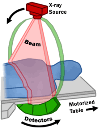
Figure 4: Spiral CT Scan (FDA, Wikipedia)
The orientation of the tunnel and the patient’s body mean that a CT radiograph shows a cross-section of the patient’s body on the axial plane, or a horizontal “slice” of the patient. This means that a scan covers all 360º of the body, allowing for better spatial recognition. These slices can be rendered to display the maximum intensity encountered by each receiver, or the average intensity, presenting tissues at different resolutions for identifying different structures. (Dalrymple, et al., 2005) Volume rendering can also be done by combining multiple radiographs to create a 3-dimensional model using edge detection technology. (Calhoun, et al., 1999) Reconstructions can also be done such that tissues can be observed from other planes. (Udupa & Herman, 1999)
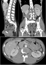
Figure 5: CT scan of abdomen and pelvis with trauma and multi-planar reconstructions (Wikipedia)
Acquisition slice thickness refers to the width of a detector row in the receiver. This can be reduced to around 1.5mm. Reducing slice thickness increases the resolution of the image formed, but leads to noisy images. More slices will also be produced. Usually, images are captured at lower slice thicknesses, but are then combined to form thicker images for analysis. The slice interval can also be changed by determining, the distance between detector rows. Intervals lower than the slice thickness would create data gaps, whereas intervals higher than it would create overlapping data, which, combined with low thickness slices, can be used for volume rendering and multi-planar reconstructions, providing high spatial resolution and image quality. (Clover Learning, 2022)
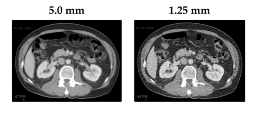
Figure 6: Comparing scans with different slice thicknesses (Clover Learning)
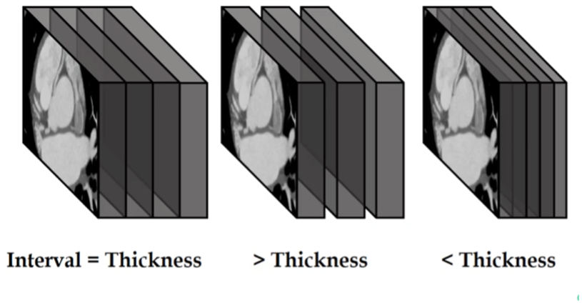
Figure 7: Slice intervals (Clover Learning)
The electron beam tomography (EBCT) scan is another form of the CT scan. An electron gun fires an electromagnet-focused beam onto 1 of 4 tungsten rings in a tunnel, creating a rotating fan of x-rays detected by the stationary receivers. Since the x-ray source is controlled electronically not mechanically, it is capable of moving at up to 40 Hz, perfect for producing high resolution and quality images of constantly moving organs like the heart and blood vessels. (Viascan of Las Colinas, TX, 2017) The patient is also exposed to lower amounts of ionizing radiation. However, EBCT scans have been criticized for producing high levels of background noise for its desired signal level, creating images that are too thin, and generally being too expensive. (Peebles, 2003)
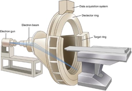
Figure 8: Electron beam CT scanner (Radiology Key)
Dual source CT scans employ 2 energies for data collection. 2 detector systems for x-rays of different energies are placed at 90º to each other. By combining data from the 2 systems, an image can be created in half a revolution. Faster imaging reduces blurring even more, and speeds up the process further. (Seidensticker & Hofmann, n.d.)
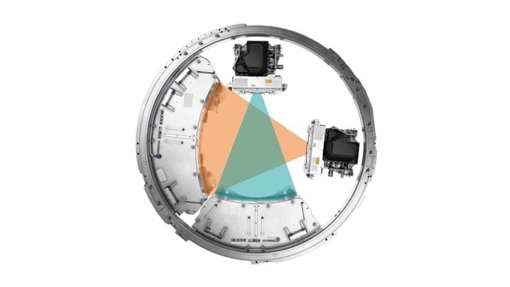
Figure 9: Structure of dual source CT scanner (Siemens Healthineers)
Iodine-based radiocontrast agents can also be injected into blood vessels before a CT scan to monitor blood flow through organs. This is especially useful for monitoring the brain, as abnormalities, such as strokes, are detected with high specificity and sensitivity. (Williams & Newby, 2016)
Some of the abnormalities CT scans are used to detect include tumors, fractures, blood clots, Crohn’s disease, kidney stones and internal bleeding. (Cleveland Clinic, n.d.) Although admittedly taking longer than traditional x-rays, CT scans can present tissues from multiple planes, and at higher resolutions, making them better than traditional radiographs. Tissues with a radiodensity difference of 1% can be distinguished. The comprehensive imaging provided by a CT scan can also replace more invasive diagnostic techniques, like catheter angiography and colonoscopies. (Wikipedia, n.d.)
However, there is still some ambiguity towards which imaging technique should definitively be used for which diagnosis. The traditional x-ray is usually the first scan doctors go for, effective for looking at major abnormalities especially in bone structure. (Fayad, LM; Johns Hopkins Medicine, n.d.) Some have mentioned that the CT scan provides better spatial resolution, useful for identifying the edges separating different structures; whereas magnetic resonance imaging (MRI) scans have better contrast resolution, allowing abnormal or cancerous tissues to be easily detected. CT scans are preferred over MRIs for patients with metal objects in their bodies like pacemakers, which may interfere with the radio waves emitted. (DeMarco, C; The University of Texas MD Anderson Cancer Center , 2023) Positron emission tomography (PET) scans are sometimes considered to be more sensitive than CT scans, and is used to observe metabolically active areas. (Cancer.Net, 2020) The nuanced difference between the different medical techniques is probably the reason why multiple scans are done for one treatment.

Figure 10: Comparing brain scans from different medical imaging techniques (San Diego Brain Injury Foundation)
CT scans can pose health risks. An abdomen and pelvis CT scan can provide the patient with an effective radiation dosage of 7.7 millisieverts, equivalent to 2.6 years of natural background radiation. (Radiology Info, n.d.) Other CT scans, like angiographies, have even higher dosages. CT scans accounted for a third of the radiation exposure in the United States in 2007. (Whaites, n.d.) Hence, there have been concerns about radiation-induced cancers. In general, a higher radiation dosage leads to higher resolution images as a higher variation of attenuation data can be produced. (Crowther, et al., n.d.) Yet as technology improves with better iterative reconstructive algorithms, such high radiation dosages may not be needed, meaning CT scans could be getting more and more safe. CT scans are usually individualized such that the radiation dose is adjusted for each patient to create a balance between health risk and image quality. (Encyclopedia Britannica, n.d.) Different body parts can be scanned separately. Additionally, there have been numerous reported cases of the adverse effects of radiocontrast agents, causing nausea, rashes or even diabetes and kidney failure. (Wikipedia, n.d.)
The CT scan is a very effective medical imaging technique, which is used in conjunction with other imaging technique for the best diagnosis, treatment and prevention of diseases. It does have some disadvantages and dangers though.
@font-face<br /> {font-family:"Cambria Math";<br /> panose-1:2 4 5 3 5 4 6 3 2 4;<br /> mso-font-charset:0;<br /> mso-generic-font-family:roman;<br /> mso-font-pitch:variable;<br /> mso-font-signature:-536870145 1107305727 0 0 415 0;}@font-face<br /> {font-family:Aptos;<br /> panose-1:2 11 0 4 2 2 2 2 2 4;<br /> mso-font-charset:0;<br /> mso-generic-font-family:swiss;<br /> mso-font-pitch:variable;<br /> mso-font-signature:536871559 3 0 0 415 0;}p.MsoNormal, li.MsoNormal, div.MsoNormal<br /> {mso-style-unhide:no;<br /> mso-style-qformat:yes;<br /> mso-style-parent:"";<br /> margin-top:0cm;<br /> margin-right:0cm;<br /> margin-bottom:8.0pt;<br /> margin-left:0cm;<br /> line-height:115%;<br /> mso-pagination:widow-orphan;<br /> font-size:12.0pt;<br /> font-family:"Aptos",sans-serif;<br /> mso-ascii-font-family:Aptos;<br /> mso-ascii-theme-font:minor-latin;<br /> mso-fareast-font-family:Aptos;<br /> mso-fareast-theme-font:minor-latin;<br /> mso-hansi-font-family:Aptos;<br /> mso-hansi-theme-font:minor-latin;<br /> mso-bidi-font-family:"Times New Roman";<br /> mso-bidi-theme-font:minor-bidi;<br /> mso-font-kerning:1.0pt;<br /> mso-ligatures:standardcontextual;<br /> mso-fareast-language:EN-US;}.MsoChpDefault<br /> {mso-style-type:export-only;<br /> mso-default-props:yes;<br /> mso-ascii-font-family:Aptos;<br /> mso-ascii-theme-font:minor-latin;<br /> mso-fareast-font-family:Aptos;<br /> mso-fareast-theme-font:minor-latin;<br /> mso-hansi-font-family:Aptos;<br /> mso-hansi-theme-font:minor-latin;<br /> mso-bidi-font-family:"Times New Roman";<br /> mso-bidi-theme-font:minor-bidi;<br /> mso-fareast-language:EN-US;}.MsoPapDefault<br /> {mso-style-type:export-only;<br /> margin-bottom:8.0pt;<br /> line-height:115%;}div.WordSection1<br /> {page:WordSection1;}
