Aerodynamics By Hand: Designing The Airfoil Before CFD

The advent of Computational Fluid Dynamics (CFD) revolutionised the way we design and optimise aircraft and analyse fluid flows. It was proposed by Lewis Fry Richardson, who wanted a way to predict weather, when he published Weather Prediction by Numerical Processing in 1922. This involved having to solve partial differential fluid flow equations like the Navier-Stokes equations, which describe the motion of liquids and gases using conservation of momentum and mass. However, the idea was far ahead of its time, and until the 70s, had little impact on aeronautics due to limited computer processing power.
That said, it is hard to imagine how aircraft were tested and built without this before the first CFD software was created. How were early engineers able to create the airfoil, all through slow and expensive wind tunnel tests and why is it so significant?
Otto Lilienthal
Before the first planes were made, the theories of heavier than air flight had yet to be proven or disproven. One of the first major pioneers was Otto Lilienthal, a German engineer. Between 1891 to 1896, he tested 2000 glider designs, accumulating around 5 hours of flight time in total. Using his experiments, he was able to produce results, such as a data table with coefficients of lift and drag. They were based upon the 1900s equation of lift, which is slightly different to ours today:
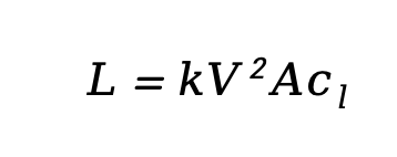
where, L= lift, k= drag coefficient, V= velocity, A= wing area, and Cl= coefficient of lift.
The Wright Brothers
The Wright brothers, early pioneers of flight, used Lilienthal’s data and his measured coefficient of lift to test their own fliers. At the time, airfoils were very rudimentary and were thin, flat and had no camber (airfoil curvature). Lilienthal’s gliders were unstable, and he had died in a crash whilst flying one of them.
However, in the test flights of their 1900 and 1901 gliders, when they used Lilienthal’s Cl value of 0.005, they underperformed compared to what was expected from the lift equation. They measured only a third of the theoretical lift. As a result, the Wright brothers decided to measure the actual values of the lift and drag coefficients themselves – they suspected an error in either Lilienthal’s camber data, or the value of the coefficient of lift he used.
To produce as controlled of an experiment as possible, they placed wing models inside a wind tunnel that they created and mounted them on a balance that measured lift and drag at the end of the tunnel. They eventually determined a lower coefficient of lift of 0.0033 for their 1901 glider’s airfoil. Using this method, having tested many different wing geometries and obtained many different values for the lift coefficient, the Wright brothers’ data clearly showed that the shape of an airfoil significantly affected the coefficient of lift.
From these experiments, they created the first lifting airfoil, which they used in their 1903 Wright Flyer, which flew an impressive 284 meters in 59 seconds.
The NACA Airfoil System
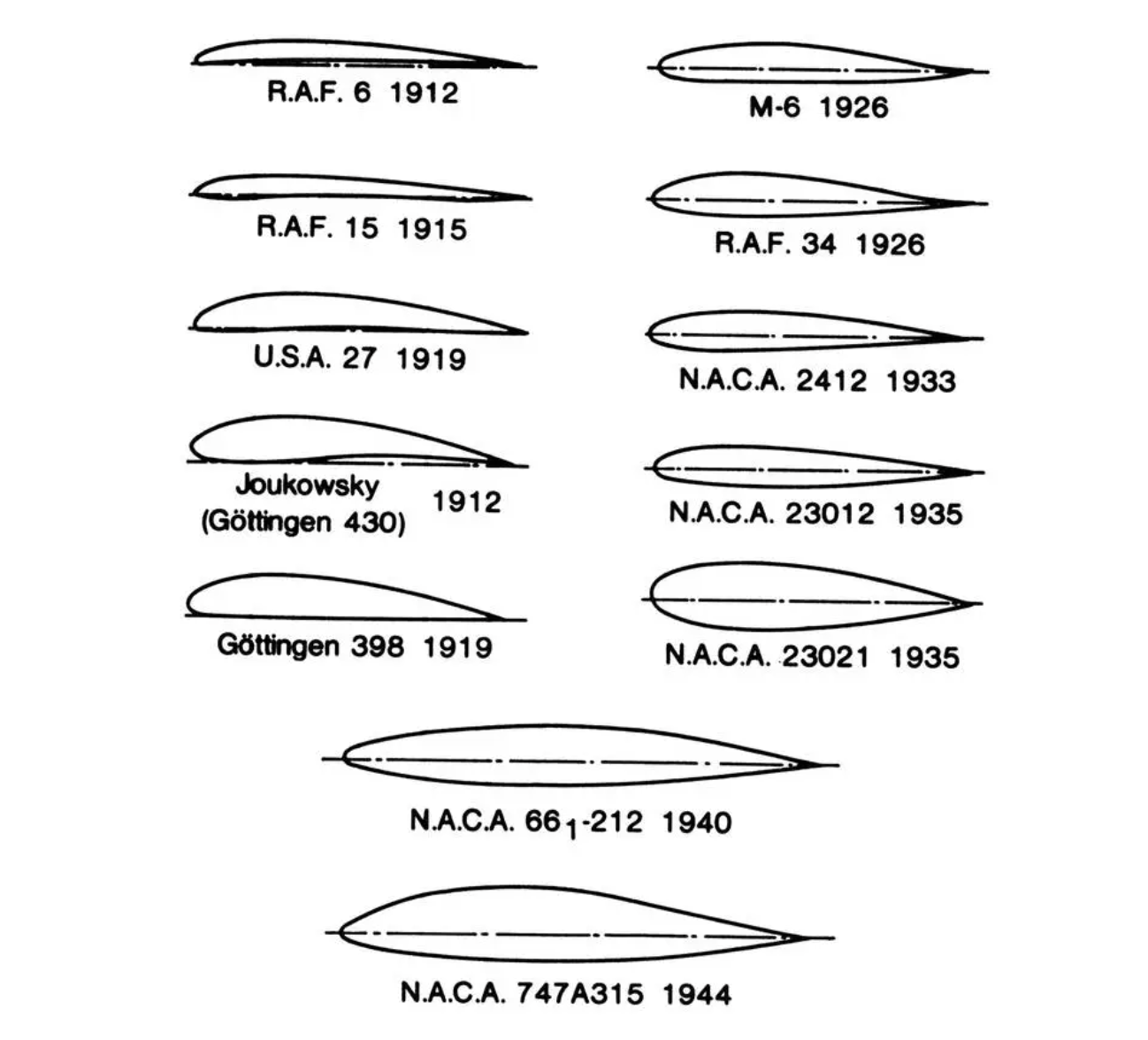
This discovery kickstarted the investigation of the effects of airfoil geometry on flight characteristics to suit the desired performance of an aircraft. In 1915, NACA (National Advisory Committee for Aeronautics), which would later become NASA post WW2 was founded. At the Langley Memorial Aeronautical Laboratory in Hampton, Virginia. There, the VDT (Variable Density Tunnel) was used to test many different airfoils. Moreover, a standardised system for the shapes of airfoils was devised using a 4 digit system; the first digit represents the maximum camber (distance of camber from the chord) as a percentage of the chord length, c; the second digit represents the position of the maximum camber along the chord, from the leading edge, in tenths of c; the last two digits represent the percentage maximum airfoil thickness of c. For example, NACA4412 has a maximum camber 0.04c, has the maximum camber 0.4c behind the leading edge, and has a maximum thickness 0.12c.
Over the years, this system has evolved, but nevertheless revolutionised aircraft design – due to vigorous testing of NACA airfoils by research institutes such as the universities of Bristol, Leicester, Sheffield and Bari, and INTA in Madrid, the aerodynamic characteristics of the different airfoils was determined. Using the previous example, the NACA4412 airfoil has been shown to be optimal for ground effect flight (increased lift and reduced drag when flying close to the ground).
NACA airfoils have been the basis for many aircraft, such as NACA2412 being the airfoil used in many Cessna civilian aircraft, having good lift generation due to a high pressure difference.
As a result, the testing of aerodynamic characteristics of standardised airfoils meant that when designing an aircraft, engineers could use a preset airfoil to suit the intended performance without having to do much expensive and time-consuming wind tunnel tests themselves.
Further Notable Developments
In addition to the NACA airfoils, several further discoveries were made through wind tunnel testing:
Laminar Flow Airfoils
In order to maximise efficiency at high airspeeds, to maintain lift, it is very important to maintain laminar flow (air moving in parallel layers with minimal mixing) above the airfoil: turbulent flow would decrease lift and increase surface friction drag. As a result, the laminar flow airfoil was created to maintain a consistently favourable pressure gradient (air pressure decreases along the airfoil) for most (30-75%) of the chord (line joining leading to trailing edge). One of the first was made for the P-51 Mustang in 1940, and along with its engines, allowed it to maintain an impressive maximum speed of around 440mph.
Supercritical Airfoils
In the 1960s-70s, NASA wanted to create an airfoil for high subsonic speeds with turbulent transonic (Mach 0.8-1.2) flow. They needed to find a way to delay the sudden increase in drag due to shockwaves forming, without sacrificing low speed and stall characteristics. After many iterations through wind tunnel testing, they were able to design the first supercritical airfoils. These are characterised by having a thick, blunt leading edge, a curved trailing edge, and a relatively flat upper surface. For example, they discovered that increasing the thickness of the trailing edge up to 0.7% of the chord length reduced the transonic drag without sacrificing low speed performance. This shape produces a weaker and more rearward shockwave to reduce drag.
Why Does This Matter?
It is easy to take for granted the fact that we can design the airfoils of wings just using CFD simulations. However, it is essential to understand how it came about from earlier, purely experimental work, in a time before the computers which make it so much easier for us today. Engineers had to use extensive wind tunnel testing, trial-and-error experimentation, and data tables. Even with the existence of CFD, it is merely a timesaving and cost-reducing tool, not a replacement for wind tunnels. Most importantly, the history of the airfoil teaches us the importance of physical testing to validate theory in the engineering process.
Bibliography
Anderson, John. Fundamentals of Aerodynamics. 6th ed., Mcgraw-Hill, 2016.
Dilşad Akgümüş Gök, and Khaled Alnimer. “Characterization of NACA 2412 and NACA 4412 Airfoils: Effects of Angle of Attack on Aerodynamics Coefficients.” Journal of Thermal Engineering, 1 Jan. 2024, pp. 1524–1538, https://doi.org/10.14744/thermal.0000892.
“From Lilienthal to the Wrights.” Www.lilienthal-Museum.de, Otto-Lilienthal-Museum Anklam, 2003, www.lilienthal-museum.de/olma/ewright.htm. Accessed 23 Feb. 2026.
“Further Gliding and Wind Tunnel Experiments - 1901.” Centennialofflight.net, 2026, www.centennialofflight.net/essay/Wright_Bros/1901/WR3.htm. Accessed 24 Feb. 2026.
Harris, Charles. NASA NASA Supercritical Airfoils a Matrix of Family-Related Airfoils. 1990.
“Laminar Flow Airfoil.” The Aviation History Online Museum, 2002, www.aviation-history.com/theory/lam-flow.htm. Accessed 24 Feb. 2026.
Lynch, Peter. The Origins of Computer Weather Prediction and Climate Modeling. 19 Mar. 2007, web.archive.org/web/20100708191309/www.rsmas.miami.edu/personal/miskandarani/Courses/MPO662/Lynch,Peter/OriginsCompWF.JCP227.pdf. Accessed 23 Feb. 2026.
Ockfen, Alex E., and Konstantin I. Matveev. “Aerodynamic Characteristics of NACA 4412 Airfoil Section with Flap in Extreme Ground Effect.” International Journal of Naval Architecture and Ocean Engineering, vol. 1, no. 1, Sept. 2009, pp. 1–12, https://doi.org/10.2478/ijnaoe-2013-0001.
P-51 Mustang Performance. Army Air Forces Material Command, 18 May 1943.
Siddique, Saad Mumtaz. “Evolution of an Airfoil.” Vintage Aviation News, 11 Dec. 2022, vintageaviationnews.com/warbird-articles/evolution-of-an-airfoil.html. Accessed 23 Feb. 2026.
Smithsonian. “Researching the Wright Way.” Airandspace.si.edu, airandspace.si.edu/explore/stories/researching-wright-way. Accessed 23 Feb. 2026.
Yassir, ABBAS, and MADBOULI Mohammed. “Implementation of the Panel Method to the Solution of Flow around Aircraft.” INCAS BULLETIN, vol. 7, no. 2, 12 June 2015, pp. 3–18, https://doi.org/10.13111/2066-8201.2015.7.2.1. Accessed 17 Oct. 2019.
![Image via [Adobe Stock]](/content/images/size/w600/2026/03/IMG_0874.jpeg)